
แสดงบทความที่มีป้ายกำกับ Circuit แสดงบทความทั้งหมด
แสดงบทความที่มีป้ายกำกับ Circuit แสดงบทความทั้งหมด
วันเสาร์ที่ 11 ธันวาคม พ.ศ. 2553
วันจันทร์ที่ 22 พฤศจิกายน พ.ศ. 2553


วันศุกร์ที่ 29 ตุลาคม พ.ศ. 2553

วันจันทร์ที่ 25 ตุลาคม พ.ศ. 2553
Battery charger circuit (9V self Oame Comment).
 วงจรชาร์จแบตเตอรี่ (9V อัตโมัติ)
Battery charger circuit (9V self Oame Comment).


Battery charger circuit board Gallery simple (constant current).
 Battery charger circuit board Gallery simple (constant current).
A simple method of charging a battery from a higher voltage battery is shown in the circuit below to the left. Only one resistor is needed to set the desired charging current and is calculated by dividing the difference in battery voltages by the charge current.

วันอาทิตย์ที่ 24 ตุลาคม พ.ศ. 2553
Help limit circuit is triggered.
 Help limit circuit is triggered.
he Schmitt Trigger oscillator below employs 3 transistors, 6 resistors and a capacitor to generate a square waveform. Pulse waveforms can be generated with an additional diode and resistor (R6). Q1 and Q2 are connected with a common emitter resistor (R1) so that the conduction of one transistor causes the other to turn off.
วงจรจุดหลอดฟลูอเรสเซนต์ 4W

The flue ballast fluorescent 4W.
C1 100uf 25V Electrolytic Capacitor
C2,C3 0.01uf 25V Ceramic Disc Capacitor
C4 0.01uf 1KV Ceramic Disc Capacitor
R1 1K 1/4W Resistor
R2 2.7K 1/4W Resistor
Q1 IRF510 MOSFET
U1 TLC555 Timer IC
T1 1 6V 300mA Transformer
LAMP 4W Fluorescent Lamp


วันเสาร์ที่ 23 ตุลาคม พ.ศ. 2553

วงจรควบคุมเสต็ปเปอร์มอเตอร์(Pepper Steak control circuit motors.)
 The circuit shown above can be used to control a unipolar stepper motor, which has FOUR coils (I've swiped it off an old fax machine). The above circuit can be for a motor current of up to about 500mA per winding wi th suitable heat sinks for the
SL100. For higher currents power transistors like 2N3055 can be used as darlington pair along with SL100. The diodes are used to protect the transistor from transients
วงจรแสดงไว้ด้านบนสามารถใช้ในการควบคุมมอเตอร์ unipolar stepper ซึ่งมีขดลวดสี่ (ฉันได้ swiped ออกจากเครื่องโทรสารเก่า) วงจรข้างต้นสามารถสำหรับยานยนต์ในปัจจุบันขึ้นไปประมาณ 500mA ต่อม้วน Wi TH อ่างความร้อนเหมาะสำหรับ SL100 สำหรับกระแสไฟฟ้าที่สูงกว่าทรานซิสเตอร์เช่น 2N3055 สามารถใช้เป็นคู่ darlington พร้อมกับ SL100 ไดโอดที่ใช้ในการป้องกันทรานซิสเตอร์จาก transients
 To reverse the motor just reverse the above sequence viz. 11,10,01,00. Alternately a 2bit UP/DOWN counter can also be used to control the direction, and a 555 multi -vibrator can be used to control the speed
หากต้องการกลับยนต์เพียงแค่กลับ ได้แก่ ลำดับข้างต้น 11,10,01,00 อีกวิธีหนึ่ง 2bit UP / DOWN เคาน์เตอร์ยังสามารถใช้ในการควบคุมทิศทางและ 555 สั่นหลายสามารถใช้ในการควบคุมความเร็ว
วงจรควบคุมรีเลย์แบบใช้มอสเฟท(Relay control circuit using a MOSFET.)
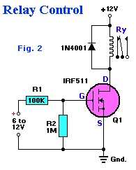
Relay control circuit using a MOSFET.



วันเสาร์ที่ 16 ตุลาคม พ.ศ. 2553
วงจรควบคุมความเร็วDC Motor 2ระดับ
 DC Motor 2-speed control circuit level.
K1, K2, K3 12V 30A SPDT Relay (See Notes)
S1, S2 SPST Switch or Button
B1, B2 12V Battery
M1 12V or 24V Motor
สมัครสมาชิก:
บทความ (Atom)


