วันศุกร์ที่ 25 มิถุนายน พ.ศ. 2553

Tube Power Amplifier with EL34


R1=470K 0,5W R13-21=820K 0.5W C8-9=0.1uF 630V
R2-5= 2K2 0.5W R14-22=5K6 0.5W C10-14=0.47uF 630V
R3=150K 0.5W R15-20= 680K 0.5W C11-13=25uF 40V
R4= 220K 0.5W R16-19=100K 0.5W V1=E80CC
R6-10= 56K 0.5W R17-18=3K3 1W V2=E80CC
R7=3.9K 0.5W R24=470R 2W V3-4=EL34
R8= 220R 0.5W TR1-2=470R 1W Variable (adj. 270?) Rectifier tube= Z2C
R9= 1M 0.5W C1-3-6-7=0.1uf 630V T1=Audio Transformer for 2x EL34 Push Pull
R11= 39K 1W C2=220pF 600v
R12-23= 180K 0.5W C4-5=16uF 550V

วันอังคารที่ 15 มิถุนายน พ.ศ. 2553

Recording circuit with IC (20 seconds)


The ISD1000A is a Direct Analog Storage device which allows you to store 20 seconds worth of voice data on an IC chip which can be play backed anytime. The data stored will stay in memory even if the power is removed. To use the circuit below simple apply power to the circuit, press the record button and hold. Speak clearly into the microphone. You have up to 20 seconds of voice message that you can store. If you talk beyond that time the chip will only store the first 20 seconds. After recording, release the record button. To playback the message, press the playback message and the message you recorded will play back. The microphone is an electret mic and the speaker is a 8 ohm speaker. If you use a 16 ohm speaker then the 10 ohm resistor marked optional, can be eliminated. This circuit can be the basis of many other larger projects. For example it could be part of an alarm circuit which plays back a voice warning when the alarm circuit is triggered.
Press the Record button to record old IC
Press Play to hear from the IC The recording one.

Audio amplifier 30W (Bipolar)

25 W Audio amplifier

25 W Audio amplifier (class A)

22 W Audio amplifier

Audio amplifier 18W

วันจันทร์ที่ 14 มิถุนายน พ.ศ. 2553

FM transmitter with 2W

This is the schematic for a FM transmitter with 2W output power that can be used between 85 and 110 MHz. Build the transmitter in a RF-proof casing, use good connectors and cable and be aware of all the other RF rules of building. Q1 and Q2 should be cooled with a heat sink. the 22pf variable capacitor is for the frequency adjustment. The another trimmer must be adjusted to maximum output power with minimum SWR and input current.
Q1,Q2
2N3866, 2SC1971 or 2N3553
L1
5 turns of 0.8 mm wireon 5 mm body with ferit core
L2
2-4 turns of ordinary Cu-PVC isolated wire over L1

วันอาทิตย์ที่ 13 มิถุนายน พ.ศ. 2553

Circuit test cable


Led's 8 Wires:
Not a mistype. The problem with testing each wire individually is that if you had 7 individually addressable LED's, then you would need an eight return or common wire. In the case of testing 8 wires you would need a ninth wire. You could use a domestic earth but its not really practical, and also if the cable was shorting to earth anyway it would be no good anyway. The solution had me thinking for a while, but since this is a logic circuit, there are only two conditions, logic high or zero. As the 4017 outputs are either high or low, any output can provide a common return path for a LED. So LED's 1 - 3 use the 4th output of the 4017, which will be zero, and the 4th LED is wired with reverse polarity. On the 4th pulse, output 4 is high, output 3 is low and so the LED will light. If the common return wire is open circuit then LEDs 1-4 will not light. A similar situation occurs with outputs 5 to 8. The common wire in can be taken from any output terminal from the 4017, but the same rule would still apply. The ability to test all wires quickly outweighs this small disadvantage. If a cable of just 4 or 6 wires is tested then it must use the wires with LED's numbered 1 to 4 or 1 to 6, which is why the LED's are numbered that way. Testing:

With a good cable and all wires connected then LED 1 will light at both cable ends, followed in sequence by LED 2 ,3, 4 etc to LED 8, the sequence then repeating. If a 4 wire cable is used, it must be connected to use the common return wire as described in the preceeding paragraph. The sequence would be LED 1,2,3,4 repeating with a delay as the 4 unused outputs are stepped through. To check for earth contact faults, the probe labeled "to earth connection" would be physically connected to a local earth. A wire that is earthing will dim or extinguish the LED's at both ends of the cable. An LED not lighting at the receiver, indicates a broken or open circuit. If two wires are short circuit, example 3 and 4 then at the receiver the sequence would be 1, 2, 34, 43, 5, 6, 7, 8. A reversal would be indicated by an out of pattern sequence of LED's. Here's an example, the probe is connected to an earth at the transmitter, the cable is very faulty, wire 1 is OK, 2 is earthing, 3 and 5 are reversed 4 is OK, 6 is open circuit and 7 and 8 are short circuit. See below.

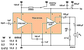
Audio amplifier 6W (IC)

5 W as an audio amplifier tube

วันเสาร์ที่ 12 มิถุนายน พ.ศ. 2553

3 Transistor amplifier circuit (50 milliwatt)

ere is a little audio amplifier similar to what you might find in a small transistor radio. The input stage is biased so that the supply voltage is divided equally across the two complimentary output transistors which are slightly biased in conduction by the diodes between the bases. A 3.3 ohm resistor is used in series with the emitters of the output transistors to stabilize the bias current so it doesn't change much with temperature or with different transistors and diodes. As the bias current increases, the voltage between the emitter and base decreases, thus reducing the conduction. Input impedance is about 500 ohms and voltage gain is about 5 with an 8 ohm speaker attached. The voltage swing on the speaker is about 2 volts without distorting and power output is in the 50 milliwatt range. A higher supply voltage and the addition of heat sinks to the output transistors would provide more power. Circuit draws about 30 milliamps from a 9 volt supply.

3 W amplifier circuit for tube

R1= 22Kohm C1-7-9= 100nF 1KV V1= ECC81
R2-3= 1Kohm C2= 220uF 350V V2= 6BX7
R4-5= 1.5Kohm C3= 150nF 400V T1= 220V@2X250V/6.3V/6.3V
R6-7= 470Kohm C4= 100uF 25V T2=Audio transformer
R8-9= 1Kohm 2W C6-8= 2X100?F 350V
RV1= 250Kohm Log. pot. D1-2= 1N4007

Audio amplifier 1W

Ese stereo amplifier

Video amplifier circuit (IC)

R1=1Kohm C2-6=100uF 25V C6=100uF 25V
R2-3=12Kohm C3=100nF 100V IC1=LM359N
R4-5-6=10Kohm C4=1pF ceramic J1-2=BNC connector
C1=10nF 100V C5=10nF 100V

วันเสาร์ที่ 5 มิถุนายน พ.ศ. 2553

วงจรเกมส์รูเล็ต( roulette game)

Tone generator circuit with IC 555


This is a basic 555 squarewave oscillator used to produce a 1 Khz tone from an 8 ohm speaker. In the circuit on the left, the speaker is isolated from the oscillator by the NPN medium power transistor which also provides more current than can be obtained directly from the 555 (limit = 200 mA). A small capacitor is used at the transistor base to slow the switching times which reduces the inductive voltage produced by the speaker. Frequency is about 1.44/(R1 + 2*R2)C where R1 (1K) is much smaller than R2 (6.2K) to produce a near squarewave. Lower frequencies can be obtained by increasing the 6.2K value, higher frequencies will probably require a smaller capacitor as R1 cannot be reduced much below 1K. Lower volume levels can be obtained by adding a small resistor in series with the speaker (10-100 ohms). In the circuit on the right, the speaker is directly driven from the 555 timer output. The series capacitor (100 uF) increases the output by supplying an AC current to the speaker and driving it in both directions rather than just a pulsating DC current which would be the case without the capacitor. The 51 ohm resistor limits the current to less than 200 mA to prevent overloading the timer output at 9 volts. At 4.5 volts, a smaller resistor can be used.

Bell sound generator circuit for switching supply

วันพฤหัสบดีที่ 3 มิถุนายน พ.ศ. 2553

วงจรกำเนิดสัญญาณาฬิกา(clock generator)


Excellent clock generator to drive 4017 type cmos circuits.
R1 = 10K to 10M, C1 = 100pF to 47uF.
Fo is (+ -)1KHz àÁ×èÍ R1=100K and C1=10nF.
Input voltage can be from 5 to 15V.

Sawtooth signal generator circuit

วงจรกำเนิดสัญญาณคลื่นรูปสี่เหลี่ยม 500 KHz ถึง 5 KHz

Square wave signal generator 500 KHz to 5 KHz.

วงจรกำเนิดสัญญาณIF 455KHz(Origin signal IF 455KHz)

Delay pulse generator with IC 555

วงจรกำเนิดน้อยส์แถบความถี่กว้าง(Noise generator Frequency width)

วงจรกำเนิดโทนเบิส(สัญาณสีเหลี่ยม)


Sound Effect Circuit

วงจรกำเนิด Pink Noise สำหรับทดสอบสัญญาณเสียง

วงจรกำนิดสัญญาณสี่เหลี่ยมแบบเปลี่ยนค่าได้(Signal circuit grip a little square)

วันพุธที่ 2 มิถุนายน พ.ศ. 2553

วงจรกันโขมย 5 จุด

วงจรกันขโมยรถยนต์

Prevent theft.

Turn back the DC Motor

Graphic E chlorinated Light Acer (10bands)


R1....20= 10Kohms C4= 10nF polyester C18= 68pF polysterine
R21....40= 1Mohms C5= 47nF polyester C19= 360pF polysterine
R41= 10Kohms C6= 4.7nF polyester C20= 36pF polysterine
R42= 1Kohms C7= 22nF polyester C21= 4.7uF polyester
R43.....52= 2.2Kohms C8= 2.2nF polyester C22-23= 33pF polysterine
R53.....62= 47Kohms C9= 12nF polyester C24= 10uF 25V
R63-64-66-67= 47Kohms C10= 1.2nF polyester C25-26= 47uF 25V
R65= 10Kohms C11= 5.6nF polyester C27...32= 47nF polyester
R68-69= 47 ohms 1/2W C12= 560pF polysterine IC1...3= TL074
RV1....10= 100Kohms lin FADER C13= 2.7nF polyester S1= 2X4 SW for stereo
RV11= 10Kohms log. C14= 270pF polysterine
C1= 180nF polyester C15= 1.5nF polyester
C2= 18nF polyester C16= 150pF polysterine
C3= 100nF polyester C17= 680pF polysterine


R1-29=100 ohms C7=220nF 100V C20=1nF 100V
R2-5-31=1Mohms C8=100nF 100V C21=560pF
R3=47Kohms C9=47nF 100V C22=270pF
R4=15Kohms C10=27nF 100V C23=150pF
R6-28=10Kohms C11=12nF 100V C25=150pF
R7....17=1Kohms C12=6.8nF 100V C26=10uF/25V
R18....27=220Kohms C13=3.3nF 100V RV1=250Kohms Lin.
C1=47uF/25V C14=68nF 100V RV2.....12=4.7Kohms Lin.
C2=47pF C15=33nF 100V IC1...3=TL074
C3=150pF C16=18nF 100V S1=2X2 SW
C4=1.5uF 100V C17=8.2nF 100V J1...3=RCA Jack
C5=820nF 100V C18=3.9nF 100V All Resitors is 1/4W 1%
C6=390nF 100V C19=2.2nF 100V

Graphic E chlorinated Light Acer (6 bands)


R1=47Kohms C2=15nF 100V C9=680nF 100V
R2-5-18=150Kohms C3=150nF 100V C10=150nF 100V
R3-4=10Kohms C4=33nF 100V C11=39nF 100V
R6....17=10Kohms C5=8.2nF 100V C12=8.2nF 100V
R19=100Kohms C6=1nF 100V C13=2.2nF 100V
RV1.....6=100Kohms Lin . C7=470pF 100V C14=470nF 100V
C1=1uF 100V C8=680nF 100V IC1-2=TL074

Graphic E chlorinated Light Acer (5 bands)


R1-4-37= 330Kohms ,R34= 15Mohms ,C12= 4.7nF 100V
R2-7= 2.2Kohms, R35-38= 220 ohms 1W ,C13= 1.5nF 100V
R3= 120Kohms ,R36= 100 ohms, C14= 470pF 100V
R5-6= 6.8Kohms ,C1-3= 1uF 40V ,C15= 68pF 100V
R8....12= 1.8Kohms, C2= 68pF 100V ,C16-19= 100nF 100V
R13....15= 200Kohms ,C4= 220uF 63V ,C17-20= 470uF 40V
R16= 180Kohms ,C5= 1uF 100V ,C18= 4.7uF 63V
R17= 150Kohms ,C6= 220nF 100V ,RV1....5= 50Kohms Lin.
R18= 1.5Kohms ,C7= 47nF 100V, Q1.....7= BC550C
R19....22= 1Kohms, C8= 15nF 100V ,S1= 2X2 SW
R23....27= 220Kohms ,C9= 5.6nF 100V .
R28....32= 15Kohms ,C10= 47nF 100V .
R33= 10Kohms ,C11= 15nF 100V .

Graphic E chlorinated Light Acer (3 bands)


R1-2= 47Kohms C1-11= 10uF 25V C8= 1.2nF 63V MKT
R3-4-5-12-13= 10Kohms C2= 33pF ceramic C9-10= 100nF 63V MKT
R6-7= 3.3Kohms C3= 2.2uF 63V MKT C12=47uF 25V
R8-9= 1.8Kohms C4= 47nF 63V MKT RV1-2= 100Kohms Lin.
R10= 270ohms C5-7= 4.7nF 63V MKT RV3= 470Kohms Lin.
R11= 22Kohms C6= 22nF 63V MKT IC1= TL072, NE5532

Click game show circuit

Activated Relay

Blogroll